Actuators
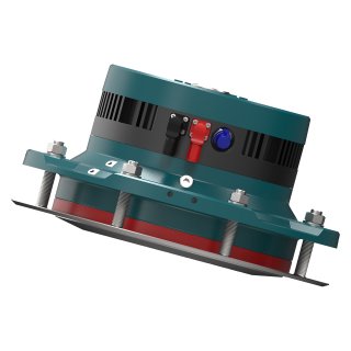
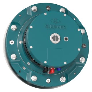
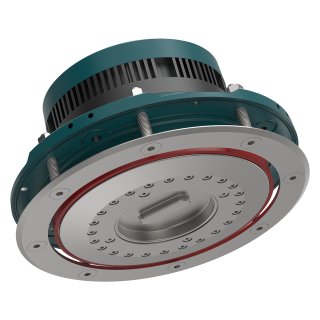
SPS40E DC Electric Stabilizer Actuator
24/48VDC
-


ANY SPEED
Vector Fins™ is the only top-performing stabilizer system for both cruising and at anchor use. The fins’ concave shape creates multilateral force direction improving the stationary positioning of a vessel while at anchor. The uniqueness of the design also becomes evident while underway as it improves in effectiveness as speed increases. Sea trials have proven that Vector Fins™ are up to 50% more efficient at anchor and capable of reducing the uncomfortable rolling motions of the vessel by up to 95% while cruising.
-


360° INSTALLATION
Designed to fit in small and challenging installation areas, the Vector Fins™ unique cone shaft design allows you to utilize the space onboard to install the actuators in any direction and insert the fins into the position you require.
Item code: SPS40E-24/48V
The SPS40E actuator is the driving force behind Sleipner’s Vector Fins™, delivering precise stabilization for compact yachts in the 14–18 meter range. Known for being the most compact and energy-efficient on the market, it integrates easily into yacht layouts, controlling fin movement to reduce roll and provide a smoother, more comfortable ride.
Powered by 24V or 48V DC, the SPS40E uses advanced algorithms to continuously adjust fin positioning in real-time, ensuring stability and comfort even in changing sea conditions.
Properties
ANY SPEED
Vector Fins™ is the only top-performing stabilizer system for both cruising and at anchor use. The fins’ concave shape creates multilateral force direction improving the stationary positioning of a vessel while at anchor. The uniqueness of the design also becomes evident while underway as it improves in effectiveness as speed increases. Sea trials have proven that Vector Fins™ are up to 50% more efficient at anchor and capable of reducing the uncomfortable rolling motions of the vessel by up to 95% while cruising.
360° INSTALLATION
Designed to fit in small and challenging installation areas, the Vector Fins™ unique cone shaft design allows you to utilize the space onboard to install the actuators in any direction and insert the fins into the position you require.

-
A legacy that commits
We’ve lived and worked with the unruly sea for a hundred years. That’s why we develop important features that enables a boat to handle the sea better – that enable you to enjoy your boat, at anchor and at full speed. That is why you wanted a boat, isn’t it?
-
Beautiful engineering
The technology in our solutions is world-class. We know, because we’ve developed it ourselves, just as we manufacture every solution, and follow them until their fixed to a hull, ourselves. This meticulous attention to detail is why your day out always will be better with a Sleipner aboard.
-
Worldwide service
We take pride in our solutions’ function throughout their lifespan. So, we never really let them out of sight, even when they’ve left for distant shores. Our global network is there to ensure continuous optimal function. You know what you get with a Sleipner, today and tomorrow.